|
Drake
|
In Drake, multibody systems with frictional contact are simulated via a discrete approximation, see Discrete Models for Simulation (while Drake also offers Continuous Models for Simulation, currently the discrete approximation performs best.) The accuracy of these discrete approximations depends on the selected time step size h. Moreover, at large enough time steps, instability problems can arise leading to unphysical intermittent contact.
To mitigate these instability problems, we introduce the concept of "margin". While margin is not a new concept ([Catto, 2013]), the way margin is used in Drake differs from its traditional purpose in game engines. Game engines such as Bullet ([Coumans, 2015; §4]) and Unity introduce margin mostly as a mechanism to mitigate pass through problems that can arise when objects move at high speeds and/or the simulation time step sizes are large in order to meet real-time requirements within a limited computational budget. In Drake however, margin is used to mitigate instability problems inherent to discrete schemes with a fixed time step size.
In the following sections we describe why we introduce margin, how we do it, and its limitations.
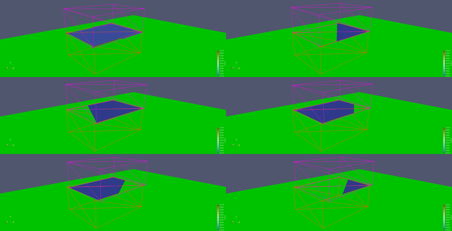
We motivate the concept of margin by considering an instability problem with the simulation in Fig. 1. Two boxes (of 0.2 m x 0.15 m x 0.08 m and mass of 0.2 kg) are stacked on top of each other. Their dynamics is simulated at a relatively large time step of 10 ms (large for robotics applications). Only their surface meshes are shown as wire frames so that we can appreciate the contact surface, colored by pressure. While we'd expect the upper box to rest stably on the lower box, we observe a wobbling instability where the contact surface shifts back and forth between two corners.
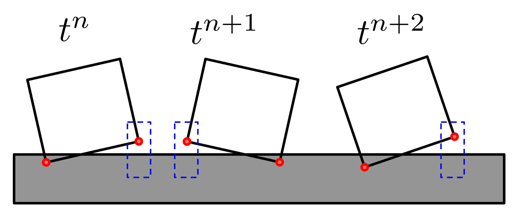
This wobbling is not physical, but rather a numerical instability. To gain insight into this problem, we analyze the simplified system in Fig. 2. In this case, contact takes place between a single box and a ground plane in 2D. In Fig. 2, we see the box at three consecutive time steps, labeled tₙ, tₙ₊₁, and, tₙ₊₂. In this simplified system, we've also simplified the contact model to a point contact model in which only the corners marked in red can make contact with the ground. At time tₙ only the left corner is in penetration. For such a configuration the contact resolution phase will predict a contact force that will attempt to minimize this interpenetration. If the time step size is large enough, the box's configuration can actually overshoot into the state sketched for tₙ₊₁. Now the box is in a new state where the right corner is in contact and the left corner is out of contact. In this configuration, the box can overshoot once again to the state at tₙ₊₂. Even more, the motion of the box can fall into a limit cycle with oscillating contact between the two corners.
The situation is more complex in Fig. 1, but the same underlying principle applies.
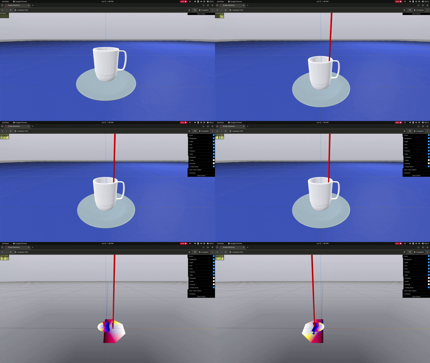
The instability arises when the stable contact between two object has a large cross-sectional area on a plane (i.e., it really doesn't happen between spheres and planes). Figure 3 shows an example of this instability for the contact between a mug placed on top of a plate. When the visuals for the geometries are turned off, we can see the two contact surfaces (table/plate and plate/table) rocking back and forth. The visualization also includes the contact forces (red) and moments (blue). In both contacts, the table contact surface is a large, flat circular patch. Even if the mug had an extruded rim on its bottom, the stable contact would be a large, planar ring-like patch, exhibiting the same behavior.
Lets consider once again the schematic in Fig. 2. At each time step, the solver only adds one constraint for each reported contact point (left or right). Satisfying this single constraint can lead to unbounded "correction". If, instead, the set of contact constraints is augmented to include both points – a point in contact and a point nearly in contact – the solver can now use this additional information to compute a force that can avoid the overshooting that leads to the instability. We are essentially adding contact constraints before contact actually happens. Whether these constraints become active or not, will ultimately depend on the contact resolution phase, which considers balance of momentum and the physics of contact. We refer to this new set of constraints as "speculative contact constraints", [Catto, 2013]. Speculative constraints are highlighted with blue boxes in Fig. 2.
To provide more context, we'll discuss briefly how the solver can use information from speculative constraints. Each contact pair will be associated with a signed distance ϕ (defined negative if objects overlap). For a compliant point contact (we discuss hydroelastic contact below) with stiffness k (we can ignore dissipation for this discussion), the normal force is modeled according to fₙ = k (-ϕ)₊, where (a)₊ = max(0, a). Notice that fₙ ≥ 0 (i.e. repulsive) always. At each time step Drake's geometry engine is invoked to compute all contact pairs at the (current) time step before contact resolution takes place (where a solver uses physics to determine the next state). Without margin, the geometry engine only reports contact pairs of geometry in penetration, with signed distances ϕ₀ < 0 (penetration) at the current time step, before contact resolution. To estimate the signed distance function ϕ (from ϕ₀) at the next state, Drake's solvers use a first order approximation as ϕ ≈ ϕ₀ + h⋅vₙ, where ϕ₀ is the signed distance at the current time step, vₙ the normal component of the (next time step) relative velocity between the two participating bodies at the contact point and h is the time step size. Using this approximation for each of the contact pairs reported by the geometry engine, Drake solvers set constraints to model the contact force as
fₙ ≈ k (-ϕ₀ - h⋅vₙ)₊, ϕ₀ < 0, (1)
where condition ϕ₀ < 0 is actually implicit by the fact that the geometry engine only reports pairs in penetration, with ϕ₀ < 0. System velocities, along with normal velocities vₙ in (1) are unknown. These are determined during the contact resolution phase along with the contact forces that satisfy the equations of motion.
To include speculative constraints, we need to allow the geometry engine to report pairs with ϕ₀ > 0 (i.e. before contact happens, as in the blue boxes in Fig. 2). To be thorough, we'd include all geometry pairs that might possibly make contact in the next time step, no matter how long distances ϕ₀ at the current step might be. However, there are good reasons to limit the set of speculative constraints:
Therefore speculative constraints between distant points are generally useless. Moreover, we'd be paying a higher O(n²) computational cost to compute and track this useless information.
Therefore, in practice we ask for a subset that only contains geometry pairs within a margin distance δ. That is, we set constraints to model forces as:
fₙ ≈ k (-ϕ₀ - h⋅vₙ)₊, ϕ₀ < δ, (2)
In the limit to δ = ∞, we'd include all pairs possibly in contact, though at a significant increase of the computational cost due to geometry. With δ = 0, no speculative constraints are considered.
Speculative contact constraints come from finding more "contact" points. When margin is zero, only those points actually in contact are reported. As margin grows, we also need to find points that are outside of contact, but within margin distance of contact. There is an increased computational cost for positive margin values in both finding those additional points as well as handling the constraints that arise from them. Tuned well, the impact of this additional computation can be negligible compared to the benefits of increased stability.
The precise value of margin is therefore determined as a trade-off between accuracy/stability and performance. Section But How Much Margin? discusses how we determine values of margin in detail.
Speculative contact constraints within a given margin fit well within a framework in terms of distance constraints — contact pairs with a distance within the margin threshold are included in the contact resolution phase. In contrast, how to introduce margin within the hydroelastic contact framework is not as straightforward.
In the hydroelastic contact model, each geometry is assigned a body-centric pressure field. The contact surface between two overlapping geometries is computed as the surface of equal hydroelastic pressure. Historically, the pressure field is defined to be zero at the surface of the geometry (no contact implies no contact pressure). Contact surfaces always have non-negative pressure and lay completely within the intersecting volume of the two colliding geometries.
To include the concept of margin, we need to extend the notion of hydroelastic contact to include imminent contact. A contact surface shouldn't be limited to the non-negative region of the pressure field but should extend into the negative region at a distance equal to the margin amount. By doing so, we can extract the necessary point data for introducing speculative constraints.
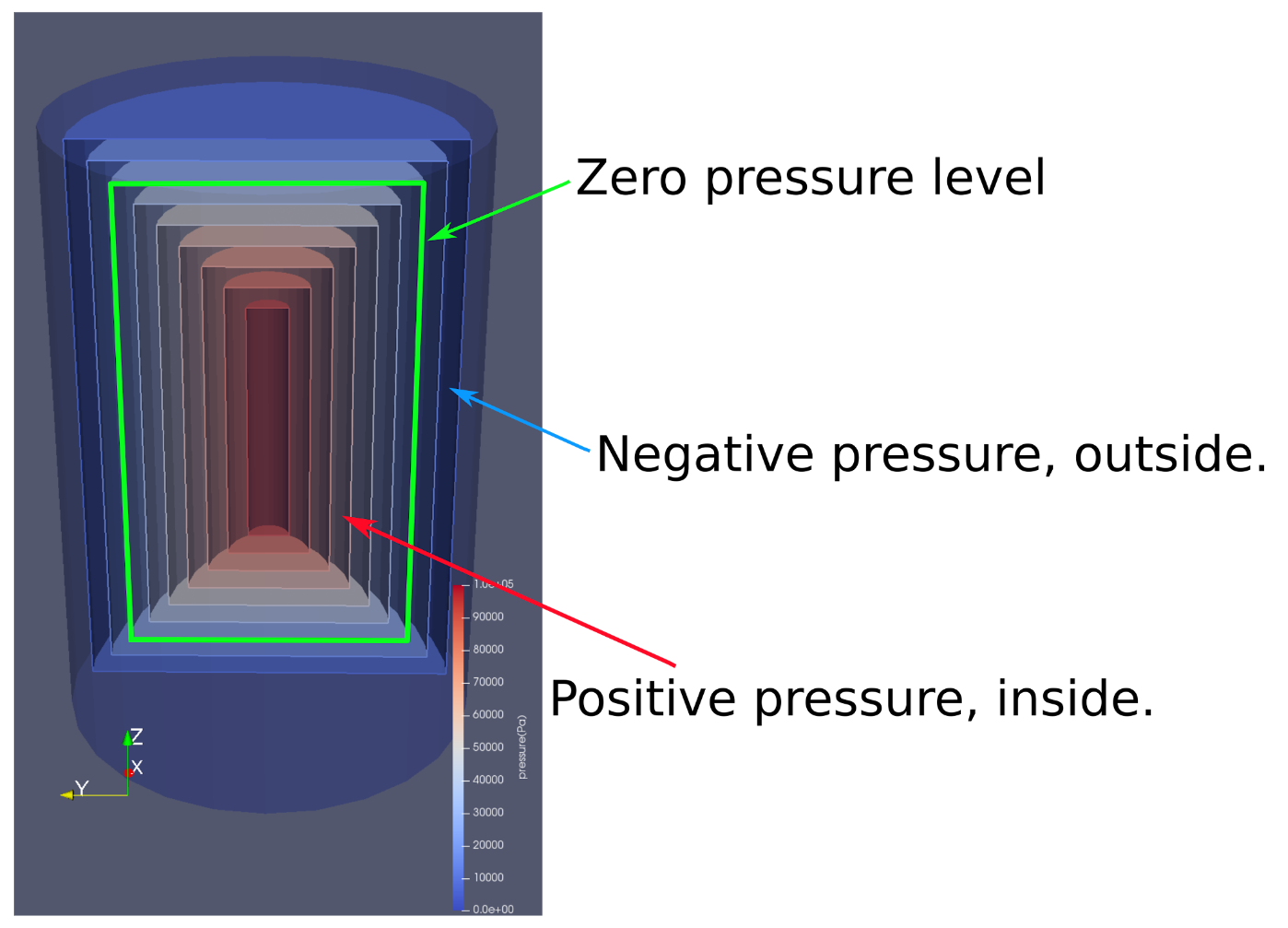
Extending the contact surface into the negative region can be done a number of ways. We chose an approach that limits the impact on computation. The goal is to increase the extent of the pressure field over which we can find contact surfaces, without increasing the cost of finding the surfaces. To that end, we replace the specified compliant hydroelastic geometry with an alternative representation whose surface is an approximation of the offset surface of the original geometry's surface (extended outward by margin distance). The pressure field defined within this "inflated" geometry is defined such that the zero level set of the pressure field is a good approximation of the original geometry's surface (where reasonably possible, it is an exact reproduction).
It's worth noting that only in a few cases are we truly producing an offset surface (spheres and capsules). For other convex primitives we approximate the offset surface of a shape with a larger shape of the same type. Non-convex shapes require additional consideration and are discussed in further detail in Non-Convex Geometries.
Figure 4 exemplifies this process for the case of a cylinder. Iso-surfaces of constant pressure, colored by pressure, are shown. The extended pressure is defined such that the zero pressure level set corresponds to the original cylinder.
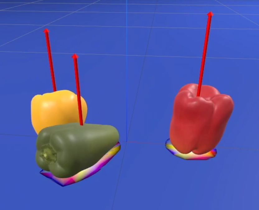
The newly inflated geometries and their extended pressure fields are then processed as any other hydroelastic fields. When the geometries (including their margin region) overlap, the contact surface is computed as the surface of equal pressure. This computation will now lead to tessellated contact surfaces with a thin "skirt", of thickness in the order of the margin, all around the contact surface where pressures are negative. Figure 5 shows peppers in contact with a blue table surface. The peppers have been modeled with a very large margin value of 1 cm to emphasize this "skirt" of negative pressure values. Normally, the contact surface would, by definition, lie completely within the pepper. Here, we can see the contact surface extending outside the pepper by about the margin distance, showing the negative pressure regime.
Similarly to the compliant point contact model in terms of signed distance, we use a first order approximation of the pressure field as p ≈ (p₀ + h⋅vₙ⋅g)₊, where p₀ is the previous time step pressure and g = ∂p/∂n is the gradient of the pressure field in the normal direction (see [Masterjohn et al., 2022]). With this, the normal force contribution from a polygon of area Δ is:
fₙ = Δ⋅(p₀ + h⋅vₙ⋅g)₊,
where for speculative constraints p₀ < 0.
Therefore, polygons with a negative pressure are processed by the contact solver as speculative constraints, and will only generate forces if the new configuration pushes these polygons into the positive pressure region. Polygons that after the resolution phase still have a negative pressure will not produce forces. As with the example of Fig. 5, the margin layer effectively increases the number of constraints, increasing the contact problem size.
For more on hydroelastic contact, including the modeling of dissipation, refer to Hydroelastic Contact.
How much margin is enough to mitigate stability problems and how does this quantity scale or depend on problem parameters such stiffness, size, etc.?
To answer this question we consider the simplified two-dimensional system in Fig. 6. This is a massless rod of length L connecting two points of mass m/2. We assume the rod to be in a limit cycle between two states, State I (shown on the left) and State II (shown on the right). Only one point is in penetration in each state. In the discrete setting, the rod is assumed to go back and forth between these two states in a single time step. The states are assumed symmetric, with the rod rotated an angle θ in State I and an angle -θ in State II. Due to this symmetry, the angular velocity to go from State II to State I is ω and the angular velocity to go from State I to State II is -ω. This analysis omits dissipation, but we believe the conclusions are still applicable in the presence of dissipation.

Since the system is in this symmetric limit cycle, the rod does not move in the vertical direction. Therefore the mean normal force due to contact must balance gravity, i.e. <fₙ> = m⋅g. Since only one point is in contact at each state, we have that <fₙ> = fₙ, where we denoted with fₙ the instantaneous normal force at one of these points. Thus fₙ = m⋅g. Notice this force value is independent of stiffness.
The rotational inertia of this system is I = m⋅L²/4. In the discrete system, the system moves between State I and State II according to the balance of momentum:
  I⋅(ω − ω₀)=h⋅fₙ⋅L/2,
  θ = θ₀ + h⋅ω,
with θ₀ and ω₀ the previous angle and angular velocity, respectively. Since the states are symmetric, ω₀ = -ω and θ₀ = -θ. Using the expressions for I and fₙ we can determine the angular velocity to be ω = h⋅g/2. The angle is then θ = h²⋅g/(2L). The total angle change is Δθ = 2⋅θ = h²⋅g/L. We can now determine the amplitude of these oscillations in signed distance as Δϕ = L⋅sin(Δθ) ≈ L⋅Δθ. Putting it all together we obtain:
Δϕ = h²⋅g. (3)
This result reveals a number of important properties for the amplitude of these oscillations:
This is a very important result, because if it holds for more complex and arbitrary geometries, it tells us that we can use a single value of the margin δ for all of our simulations (for as long as we are on the same planet).
In the analysis of the simple rod system in Fig. 6, we realize that these oscillations can be mitigated completely if at each time step we consider both the left and right contact points when solving the contact problem at each time step. Moreover, the analysis tells us that for more complex systems, it is not really necessary to consider all O(n²) geometry pairs in the scene, but really only those that are within a distance in the order of the estimated amplitude of the vibrations, i.e. O(h²⋅g).
With this in mind, we then expect that if δ = O(h²⋅g), then these spurious oscillations will be mitigated. We verify this idea in the original system of Fig. 1, with a wide range of margin values. To test a very adversarial situation we use E = 10⁹ Pa (as explained above, compliance helps mitigate these instabilities). For each contact constraint we measure the signed distance ϕ and compute its standard deviation σ(|ϕ|) as a metric to characterize the amplitude of these spurious oscillations. Since h² changes several orders of magnitude, and guided by (3), we plot in Fig. 7 the dimensionless amplitude σ(|ϕ|) / (h²⋅g).
Finally, notice we use δ / (h²⋅g) for the horizontal axis. This is again guided by (3), which predicts that values of margin δ effective at mitigating oscillations are order h². We observe in Fig. 7 that indeed for δ / (h²⋅g) ≳ 1 the instabilities die off.
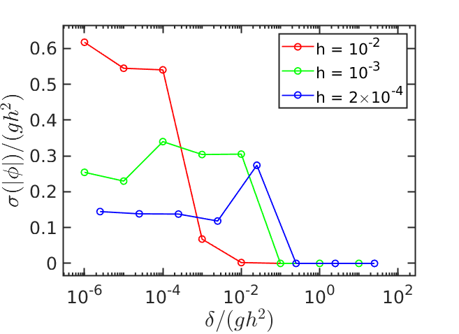
Once again, keep in mind that the rod analysis is very simplified. For instance, notice in Fig. 7 that at larger time steps margin δ is more effective yet (requiring only δ / (h²⋅g) ≳ 0.01 for oscillations to die off). This can be explained by the numerical dissipation introduced by discrete schemes, which is not taken into account in our simplified analysis, and goes away as time step is decreased.
Figure 7 indicates that for time steps [10⁻², 10⁻³, 2×10⁻⁴] (seconds) that the oscillation disappeared with δ / (h²⋅g) ≈ [10⁻², 10⁻¹, 10⁻¹], respectively. Given those values, we can solve for margin values of δ = [10⁻⁵, 10⁻⁶, 4×10⁻⁸] (meters), respectively. The worst case comes from the largest margin, 10⁻⁵ m (most expensive computation). To account for factors not included in our analysis, we in general choose the very conservative value of δ = 10⁻⁴ m. We confirmed the effectiveness of this value over and over again with additional experimentation on more complex systems as those in Figs. 3 and 5. While incredibly effective, notice how small this value is.
TODO: write.
The following sections cover more advanced material not really essential for the general understanding and effective use of margin and speculative contact constraints in Drake. We provide this material for completeness since many advanced users might find it useful.
TODO: Write this.
The result in (3) predicts the magnitude of contact oscillations in the absence of margin (δ = 0) for the simplified system of Fig. 6. The estimation predicts Δϕ = h²⋅g. This estimate will not hold exactly for arbitrary geometries and mass distributions. The expectation, however, is that the scaling Δϕ ~ h²⋅g still does provide a good estimate of the magnitude of these spurious oscillations.
The aim of this section is to verify to what extent this scaling does provide a good estimate of the amplitude of these oscillations in a more complex case. We are particularly interested not only to understand to what extent the scaling law applies to this system but even more so, to verify the independence of these results with parameters such as stiffness and mass (the simplified case was actually shown to be independent of these parameters). If (3) happens to provide a good estimate, then we have a very good chance of success at choosing a value of margin δ for arbitrary simulation cases.
For a general contact problem, many physical and numerical parameters are involved:
To start somewhere, we fix the shapes we use, and choose as our first study case the stack of boxes we started with, Fig. 1. To verify (3), we'd need to scan this high dimensional space of parameters, a daunting task. To make this tractable we resource the incredibly powerful tool of dimensional analysis. This method reduces the dimension of the parameter space by finding an alternative (smaller) set of dimensionless parameters. The underlying method is described by Buckingham π theorem, though in practice selecting these parameters often requires a great deal of experience and physical intuition. We won't go into detail here, but let's consider a common example in fluid dynamics. While the drag force a fluid exerts on an object is an incredibly complex function of density, viscosity, flow speed, geometry and size, engineers make very useful plots involving two (now very popular) dimensionless quantities: drag coefficient vs. Reynolds number. We therefore use the same procedure to find two dimensionless parameters that can succinctly capture the physics (and numerics in this case) of the problem at hand.
We start by defining an effective spring stiffness as k = E⋅A/H, with E the hydroelastic modulus, A the area of contact (in our case the area of the base of the box), and H the Elastic Foundation depth (in our case half of the boxes minimum side length). With this, we can define the (angular) frequency ω = (k/m)¹ᐟ², similar to a spring-mass system, where m is the mass of the box. This frequency characterizes the dynamics of the compliant contact, and our intuition tells us it should be an important quantity in the analysis. With this, we define our first dimensionless parameter: π₁ = h⋅ω = h⋅(k/m)¹ᐟ².
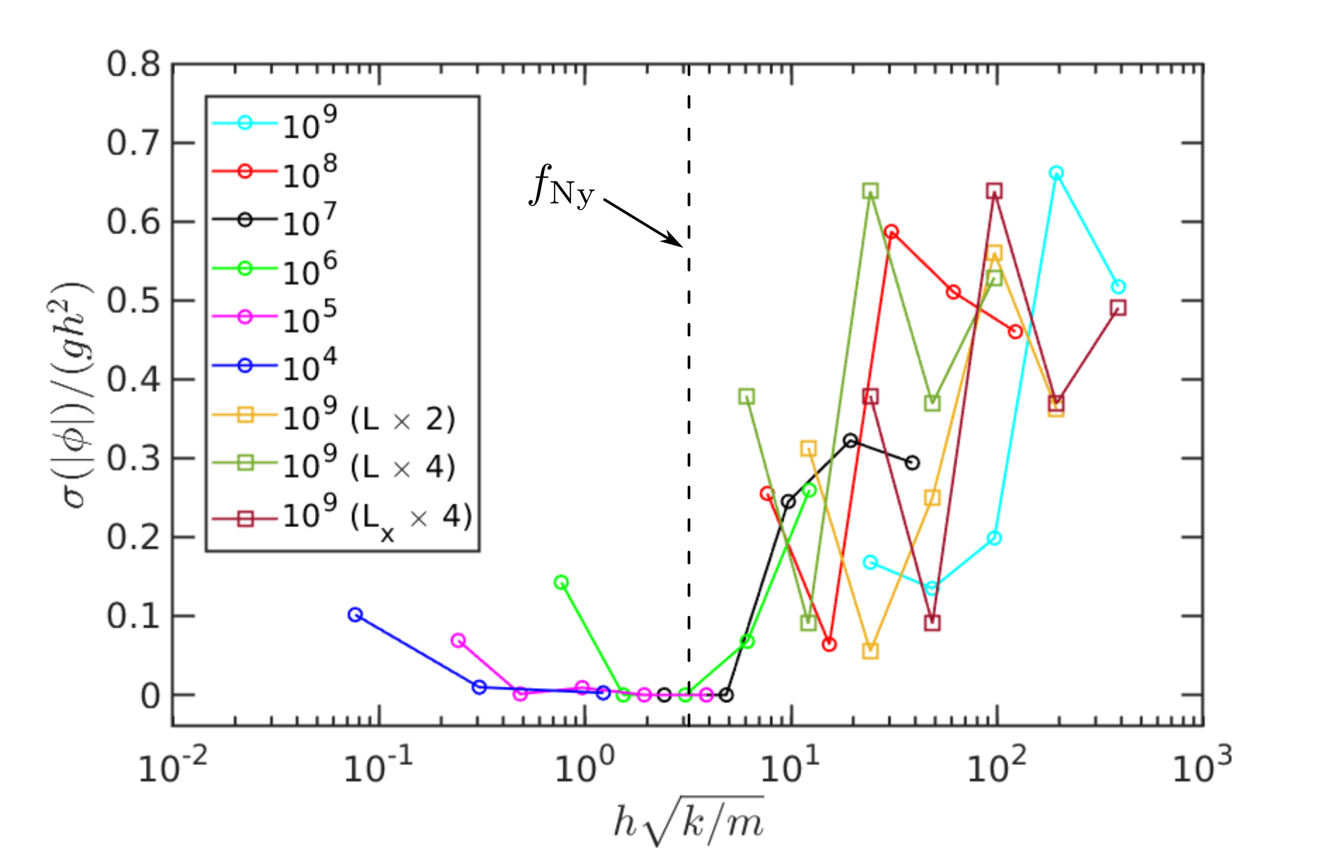
Our second parameter must involve the amplitude of the oscillations. Guided by our estimation in (3), we define π₂ = σ(|ϕ|) / (h²⋅g), where to characterize the amplitude of the oscillations we measure the standard deviation σ(|ϕ|) of the penetrations.
Having identified these two dimensionless parameters, we now run a large number of simulations, sampling the parameter space (E, m, sizes, h). We then measure σ(|ϕ|) for each, compute π₁ and π₂ and plot them with the hope to find a clear relationship among them.
The parameters we sweep are:
All simulations use a non-zero Hunt & Crossley dissipation d = 20 s/m to keep the rattling instability somewhat under control to avoid the upper box from drifting and falling to the side.
We plot σ(|ϕ|) / (h²⋅g) in Fig. 8. Labels correspond to hydroelastic modulus E, and in parentheses to size and shape changes. The very first thing we observe clearly is that oscillations die off below a frequency close to the Nyquist frequency (= 1/(2h), or h⋅(k/m)¹ᐟ² = π). This makes sense, as the dynamics of contact is resolved by the simulation time step, the numerical method is able to recover from this spurious oscillatory behavior. We note that the increase we observe at the smaller values of π₁ = h⋅ω is only an artifact of the simulations not reaching yet a steady state; compliance is so low that with the dissipation used boxes are still settling.
Second, we observe that oscillations develop at frequencies higher than the Nyquist frequency; time step is not small enough to resolve the dynamics of the compliant contact. While (3) predicts a constant value in this regime, we observe for this case (dimensionless) amplitudes in the range π₂ ∈ (0.1, 0.6). This might seem like a large discrepancy with the simplified analysis, but it's quite the opposite! Keep in mind this is a significantly more complex system than the one in Fig. 6 and that parameters change order of magnitude over a wide range. Even for this case, estimating the amplitude of these vibrations with ~h²⋅g, provides a good approximation.
