|
Drake
|
|
Drake
|
This ForceElement models a massless flexible bushing that connects a frame A of a link (body) L0 to a frame C of a link (body) L1.
The bushing can apply a torque and force due to stiffness (spring) and dissipation (damper) properties. Frame B is the bushing frame whose origin Bo is halfway between Ao (A's origin) and Co (C's origin) and whose unit vectors 𝐁𝐱, 𝐁𝐲, 𝐁𝐳 are "halfway" (in an angle-axis sense) between the unit vectors of frame A and frame C. Frame B is a "floating" frame in the sense that it is calculated from the position and orientation of frames A and C (B is not welded to the bushing).
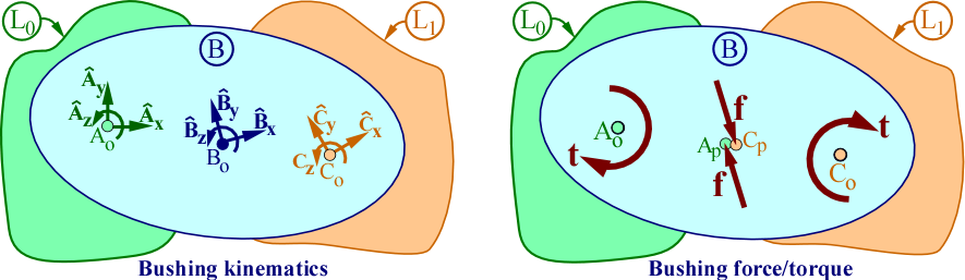
The set of forces on frame C from the bushing is equivalent to a torque 𝐭 on frame C and a force 𝐟 applied to a point Cp of C. The set of forces on frame A from the bushing is equivalent to a torque −𝐭 on frame A and a force −𝐟 applied to a point Ap of A. Points Ap and Cp are coincident with Bo (frame B's origin).
This "quasi-symmetric" bushing force/torque model was developed at Toyota Research Institute and has advantages compared to traditional bushing models because it employs a bushing-centered "symmetric" frame B and it ensures the moment of −𝐟 on A about Ao is equal to the moment of 𝐟 on C about Co. Traditional models differ as they lack a "symmetric" frame B and apply −𝐟 at Ao, which means the moment of −𝐟 on A about Ao is always zero. Note: This bushing model is not fully symmetric since the orientation between frames A and C is parameterized with roll-pitch-yaw angles [q₀ q₁ q₂]. Since these angles have an inherent sequence, they are not mathematically symmetric.
The torque model depends on spring-damper "gimbal" torques τ ≜ [τ₀ τ₁ τ₂] which themselves depend on roll-pitch-yaw angles q ≜ [q₀ q₁ q₂] and rates q̇ = [q̇₀ q̇₁ q̇₂] via a diagonal torque-stiffness matrix K₀₁₂ and a diagonal torque-damping matrix D₀₁₂ as
    ⌈ τ₀ ⌉     ⌈k₀    0    0⌉ ⌈ q₀ ⌉     ⌈d₀    0    0⌉ ⌈ q̇₀ ⌉
τ ≜ | τ₁ | = − | 0   k₁    0| | q₁ |  −  | 0   d₁    0| | q̇₁ |
    ⌊ τ₂ ⌋     ⌊ 0    0   k₂⌋ ⌊ q₂ ⌋     ⌊ 0    0   d₂⌋ ⌊ q̇₂ ⌋
where k₀, k₁, k₂ and d₀, d₁, d₂ are torque stiffness and damping constants and must have non-negative values.
The bushing model for the net force 𝐟 on frame C from the bushing depends on scalars x, y, z which are defined so 𝐫 (the position vector from Ao to Co) can be expressed in frame B as 𝐫 ≜ p_AoCo = [x y z]ʙ = x 𝐁𝐱 + y 𝐁𝐲 + z 𝐁𝐳. The model for 𝐟 uses a diagonal force-stiffness matrix Kxyᴢ, a diagonal force-damping matrix Dxyᴢ, and defines fx, fy, fz so 𝐟 = [fx fy fz]ʙ.
⌈ fx ⌉      ⌈kx    0    0⌉ ⌈ x ⌉     ⌈dx    0    0⌉ ⌈ ẋ ⌉
| fy | =  − | 0   ky    0| | y |  −  | 0   dy    0| | ẏ |
⌊ fz ⌋      ⌊ 0    0   kz⌋ ⌊ z ⌋     ⌊ 0    0   dz⌋ ⌊ ż ⌋
where kx, ky, kz and dx, dy, dz are force stiffness and damping constants and must have non-negative values.
This bushing's constructor sets the torque stiffness/damping constants [k₀ k₁ k₂] and [d₀ d₁ d₂] and the force stiffness/damping constants [kx ky kz] and [dx dy dz]. The examples below demonstrate how to model various joints that have a flexible (e.g., rubber) mount. The damping values below with ? may be set to 0 or a reasonable positive number.
| Bushing type | torque constants | force constants |
|---|---|---|
| z-axis revolute joint | k₀₁₂ = [k₀ k₁ 0] | kxyz = [kx ky kz] |
| d₀₁₂ = [d₀ d₁ ?] | dxyz = [dx dy dz] | |
| x-axis prismatic joint | k₀₁₂ = [k₀ k₁ k₂] | kxyz = [0 ky kz] |
| d₀₁₂ = [d₀ d₁ d₂] | dxyz = [? dy dz] | |
| Ball and socket joint | k₀₁₂ = [0 0 0] | kxyz = [kx ky kz] |
| d₀₁₂ = [? ? ?] | dxyz = [dx dy dz] | |
| Weld/fixed joint | k₀₁₂ = [k₀ k₁ k₂] | kxyz = [kx ky kz] |
| d₀₁₂ = [d₀ d₁ d₂] | dxyz = [dx dy dz] |
Angles q₀, q₁, q₂ are calculated from frame C's orientation relative to frame A, with [−π < q₀ ≤ π, −π/2 ≤ q₁ ≤ π/2, −π < q₂ ≤ π], hence, there is no angle wrapping and torque stiffness has a limited range. Gimbal torques τ can be discontinuous if one of q₀, q₁, q₂ is discontinuous and its associated torque spring constant is nonzero. For example, τ₂ is discontinuous if k₂ ≠ 0 and the bushing has a large rotation so q₂ jumps from ≈ −π to π. τ can also be discontinuous if one of q̇₀, q̇₁, q̇₂ is discontinuous and its associated torque damper constant is nonzero. For example, τ₀ is discontinuous if d₀ ≠ 0 and q̇₀ is undefined (which occurs when pitch = q₁ = π/2). Note: Due to the relationship of 𝐭 to τ shown below, 𝐭 is discontinuous if τ is discontinuous.
As shown below, there are multiple ways to estimate torque and force stiffness and damping constants. Use a method or combination of methods appropriate for your application. For example, some methods are more useful for a real physical bushing whereas other methods (called "penalty methods") can be more useful when replacing an ideal joint (such as a revolute or fixed/weld joint) with a bushing.
Consider a penalty method if you want a bushing to substitute for a "hard" constraint (e.g., an ideal joint). Since a bushing is inherently compliant it will violate a hard constraint somewhat. The stiffer the bushing, the more accurately it enforces the hard constraint, but at a cost of more computational time. To balance accuracy versus time, consider your tolerance for constraint errors. For example, is it OK for your bushing to displace xₘₐₓ = 1 mm for an estimated Fxₘₐₓ = 100 N? Also, one way to choose a force damping constant dx is by choosing a "reasonably small" settling time tₛ, where settling time tₛ is the interval of time for a system to settle to within 1% (0.01) of an equilibrium solution). Is tₛ = 0.01 s negligible for a robot arm with a 10 s reach maneuver?
The estimate of stiffness k₀ depends on whether you are modeling a physical bushing (consider stiffness methods 1 or 2 below) or whether you are using a bushing to replace an ideal joint such as a revolute or fixed/weld joint (consider stiffness "penalty methods" 3 or 4 below).
The estimate of damping d₀ depends on whether you are modeling a physical bushing (consider damping method 1 below) or whether you are using a bushing to enforce a constraint (consider damping methods 2 or 3 below).
Refer to Advanced bushing stiffness and damping for more details.
The estimate of stiffness kx depends on whether you are modeling a real bushing (consider stiffness methods 1 or 2 below) or whether you are using a bushing to replace an ideal joint such as a revolute or fixed/weld joint (consider stiffness "penalty methods" 3 or 4 below).
The estimate of damping dx depends on whether you are modeling a physical bushing (consider damping method 1 below) or whether you are using a bushing to enforce a constraint (consider damping methods 2 or 3 below).
Refer to Advanced bushing stiffness and damping for more details.
To understand how "gimbal torques" τ relate to 𝐭, it helps to remember that the RollPitchYaw class documentation states that a Space-fixed (extrinsic) X-Y-Z rotation with roll-pitch-yaw angles [q₀ q₁ q₂] is equivalent to a Body-fixed (intrinsic) Z-Y-X rotation by yaw-pitch-roll angles [q₂ q₁ q₀]. In the context of "gimbal torques", the Body-fixed Z-Y-X rotation sequence with angles [q₂ q₁ q₀] is physically meaningful as it produces torques associated with successive frames in a gimbal as τ₂ 𝐀𝐳, τ₁ 𝐏𝐲, τ₀ 𝐂𝐱, where each of 𝐀𝐳, 𝐏𝐲, 𝐂𝐱 are unit vectors associated with a frame in the yaw-pitch-roll rotation sequence and 𝐏𝐲 is a unit vector of the "pitch" intermediate frame. As described earlier, torque 𝐭 is the moment of the bushing forces on frame C about Cp. Scalars tx, ty, tz are defined so 𝐭 can be expressed 𝐭 = [tx ty tz]ᴀ = tx 𝐀𝐱 + ty 𝐀𝐲 + tz 𝐀𝐳. As shown in code documentation, the relationship of [tx ty tz] to [τ₀ τ₁ τ₂] was found by equating 𝐭's power to τ's power as 𝐭 ⋅ w_AC = τ ⋅ q̇.
⌈ tx ⌉      ⌈ τ₀ ⌉            ⌈ cos(q₂)/cos(q₁)  sin(q₂)/cos(q₁)   0 ⌉
| ty | = Nᵀ | τ₁ |  where N = |   −sin(q2)            cos(q2)      0 |
⌊ tz ⌋      ⌊ τ₂ ⌋            ⌊ cos(q₂)*tan(q₁)   sin(q₂)*tan(q₁)  1 ⌋
The basics on how to choose bushing stiffness and damping constants are at:
The list below provides more detail on: The performance tradeoff between high stiffness and long simulation time; loads that affect estimates of Mxₘₐₓ or Fxₘₐₓ; and how a linear 2ⁿᵈ-order ODE provides insight on how to experimentally determine stiffness and damping constants.
 m ẍ +     dx ẋ +  kx x = 0   or alternatively as
   ẍ + 2 ζ ωₙ ẋ + ωₙ² x = 0   where ωₙ² = kx/m,  ζ = dx / (2 √(m kx))
ωₙ and ζ also appear in the related ODEs for rotational systems, namely
 I₀ q̈ +     d₀ q̇ +  k₀ q = 0   or alternatively as
    q̈ + 2 ζ ωₙ q̇ + ωₙ² q = 0   where ωₙ² = k₀/I₀,  ζ = d₀ / (2 √(I₀ k₀))
One way to determine ωₙ is from settling time tₛ which approximates the time for a system to settle to within a specified settling ratio of an equilibrium solutions. Typical values for settling ratio are 1% (0.01), 2% (0.02), 5% (0.05), and 10% (0.10).| Settling ratio | ωₙ |
|---|---|
| 0.01 | 6.64 / tₛ |
| 0.02 | 5.83 / tₛ |
| 0.05 | 4.74 / tₛ |
| 0.10 | 3.89 / tₛ |
Since a literature reference for this formula was not found, the derivation below was done at TRI (it has not been peer reviewed). This formula results from the "dominant pole" solution in the prototypical constant-coefficient linear 2ⁿᵈ-order ODE. For ẋ(0) = 0, mathematics shows poles p₁ = -ωₙ s₁, p₂ = -ωₙ s₂, where sz = √(ζ² - 1), s₁ = ζ - sz, s₂ = ζ + sz. and
 x(t) / x(0) = p₂/(p₂-p₁) exp(p₁ t) - p₁/(p₂-p₁) exp(p₂ t)
             = s₂/(s₂-s₁) exp(p₁ t) - s₁/(s₂-s₁) exp(p₂ t)
             =  k/( k-1 ) exp(p₁ t) -  1/( k-1 ) exp(p₂ t) where k = s₂ / s₁
             ≈  k/( k-1 ) exp(p₁ t)                        since p₁ > p₂
Note: k = s₂ / s₁ is real, k > 0, s₂ = k s₁, and p₁ > p₂ (p₁ is less negative then p₂), so exp(p₁ t) decays to zero slower than exp(p₂ t) and exp(p₁ t) ≫ exp(p₂ t) for sufficiently large t. Hence we assume exp(p₂ t) ≈ 0 (which is why p₁ is called the "dominant pole"). Next,
  k/(k - 1) = s₂ / s₁ / (s₂/s₁ -1) = s₂ / (s₂ - s₁) = s₂ / (2 sz),  so
  x(t) / x(0)  ≈  s₂ / (2 sz) exp(-s₁ ωₙ t),                        hence
  settling_ratio ≈ s₂ / (2 sz) exp(-s₁ ωₙ tₛ),                      finally
  ωₙ ≈ -ln(settling_ratio 2 sz / s₂) / (s₁ tₛ)
The table below shows that there is little error in this approximate formula for various settling ratios and ζ, particularly for ζ ≥ 1.1. For 1.0 ≤ ζ < 1.1, the critical damping estimates of ωₙ work well.
| Settling ratio | ζ = 1.01 | ζ = 1.1 | ζ = 1.2 | ζ = 1.3 | ζ = 1.5 |
|---|---|---|---|---|---|
| 0.01 | 1.98% | 0.005% | 2.9E-5% | 1.6E-7% | 2.4E-12% |
| 0.02 | 2.91% | 0.016% | 1.8E-4% | 2.1E-6% | 1.6E-10% |
| 0.05 | 5.10% | 0.076% | 2.3E-3% | 7.0E-5% | 4.4E-8% |
| 0.10 | 8.28% | 0.258% | 1.6E-2% | 1.0E-3% | 3.3E-6% |
Note: There is a related derivation in the reference below, however, it needlessly makes the oversimplified approximation k/(k - 1) ≈ 1. https://electronics.stackexchange.com/questions/296567/over-and-critically-damped-systems-settling-time
| T | The underlying scalar type. Must be a valid Eigen scalar. |
#include <drake/multibody/tree/linear_bushing_roll_pitch_yaw.h>
Public Member Functions | |
| LinearBushingRollPitchYaw (const Frame< T > &frameA, const Frame< T > &frameC, const Vector3< double > &torque_stiffness_constants, const Vector3< double > &torque_damping_constants, const Vector3< double > &force_stiffness_constants, const Vector3< double > &force_damping_constants) | |
| Construct a LinearBushingRollPitchYaw B that connects frames A and C, where frame A is welded to a link L0 and frame C is welded to a link L1. | |
| ~LinearBushingRollPitchYaw () override | |
| const RigidBody< T > & | link0 () const |
| Returns link (body) L0 (frame A is welded to link L0). | |
| const RigidBody< T > & | link1 () const |
| Returns link (body) L1 (frame C is welded to link L1). | |
| const Frame< T > & | frameA () const |
| Returns frame A, which is the frame that is welded to link (body) L0 and attached to the bushing. | |
| const Frame< T > & | frameC () const |
| Returns frame C, which is the frame that is welded to link (body) L1 and attached to the bushing. | |
| const Vector3< double > & | torque_stiffness_constants () const |
| Returns the default torque stiffness constants [k₀ k₁ k₂] (units of N*m/rad). | |
| const Vector3< double > & | torque_damping_constants () const |
| Returns the default torque damping constants [d₀ d₁ d₂] (units of N*m*s/rad). | |
| const Vector3< double > & | force_stiffness_constants () const |
| Returns the default force stiffness constants [kx ky kz] (units of N/m). | |
| const Vector3< double > & | force_damping_constants () const |
| Returns the default force damping constants [dx dy dz] (units of N*s/m). | |
| SpatialForce< T > | CalcBushingSpatialForceOnFrameA (const systems::Context< T > &context) const |
| Calculate F_A_A, the bushing's spatial force on frame A expressed in A. | |
| SpatialForce< T > | CalcBushingSpatialForceOnFrameC (const systems::Context< T > &context) const |
| Calculate F_C_C, the bushing's spatial force on frame C expressed in C. | |
Does not allow copy, move, or assignment | |
| LinearBushingRollPitchYaw (const LinearBushingRollPitchYaw &)=delete | |
| LinearBushingRollPitchYaw & | operator= (const LinearBushingRollPitchYaw &)=delete |
| LinearBushingRollPitchYaw (LinearBushingRollPitchYaw &&)=delete | |
| LinearBushingRollPitchYaw & | operator= (LinearBushingRollPitchYaw &&)=delete |
| Vector3< T > | GetTorqueStiffnessConstants (const systems::Context< T > &context) const |
| The following set of methods allow for access and modification of torque/force stiffness/damping parameters stored in a systems::Context. | |
| Vector3< T > | GetTorqueDampingConstants (const systems::Context< T > &context) const |
| Returns the torque damping constants [d₀ d₁ d₂] (units of N*m*s/rad) stored in context. | |
| Vector3< T > | GetForceStiffnessConstants (const systems::Context< T > &context) const |
| Returns the force stiffness constants [kx ky kz] (units of N/m) stored in context. | |
| Vector3< T > | GetForceDampingConstants (const systems::Context< T > &context) const |
| Returns the force damping constants [dx dy dz] (units of N*s/m) stored in context. | |
| void | SetTorqueStiffnessConstants (systems::Context< T > *context, const Vector3< T > &torque_stiffness) const |
| Sets the torque stiffness constants [k₀ k₁ k₂] (units of N*m/rad) in context. | |
| void | SetTorqueDampingConstants (systems::Context< T > *context, const Vector3< T > &torque_damping) const |
| Sets the torque damping constants [d₀ d₁ d₂] (units of N*m*s/rad) in context. | |
| void | SetForceStiffnessConstants (systems::Context< T > *context, const Vector3< T > &force_stiffness) const |
| Sets the force stiffness constants [kx ky kz] (units of N/m) in context. | |
| void | SetForceDampingConstants (systems::Context< T > *context, const Vector3< T > &force_damping) const |
| Sets the force damping constants [dx dy dz] (units of N*s/m) in context. | |
| Public Member Functions inherited from ForceElement< T > | |
| ForceElement (ModelInstanceIndex model_instance) | |
| Default constructor for a generic force element. | |
| ~ForceElement () override | |
| ForceElementIndex | index () const |
| Returns this element's unique index. | |
| void | CalcAndAddForceContribution (const systems::Context< T > &context, const internal::PositionKinematicsCache< T > &pc, const internal::VelocityKinematicsCache< T > &vc, MultibodyForces< T > *forces) const |
| (Advanced) Computes the force contribution for this force element and adds it to the output arrays of forces. | |
| ForceElement (const ForceElement &)=delete | |
| ForceElement & | operator= (const ForceElement &)=delete |
| ForceElement (ForceElement &&)=delete | |
| ForceElement & | operator= (ForceElement &&)=delete |
| Public Member Functions inherited from MultibodyElement< T > | |
| virtual | ~MultibodyElement () |
| ModelInstanceIndex | model_instance () const |
| Returns the ModelInstanceIndex of the model instance to which this element belongs. | |
| template<typename = void> | |
| const MultibodyPlant< T > & | GetParentPlant () const |
| Returns the MultibodyPlant that owns this MultibodyElement. | |
| void | DeclareParameters (internal::MultibodyTreeSystem< T > *tree_system) |
| Declares MultibodyTreeSystem Parameters at MultibodyTreeSystem::Finalize() time. | |
| void | SetDefaultParameters (systems::Parameters< T > *parameters) const |
| Sets default values of parameters belonging to each MultibodyElement in parameters at a call to MultibodyTreeSystem::SetDefaultParameters(). | |
| void | DeclareDiscreteState (internal::MultibodyTreeSystem< T > *tree_system) |
| Declares MultibodyTreeSystem discrete states. | |
| void | DeclareCacheEntries (internal::MultibodyTreeSystem< T > *tree_system) |
| (Advanced) Declares all cache entries needed by this element. | |
| bool | is_ephemeral () const |
| Returns true if this MultibodyElement was added during Finalize() rather than something a user added. | |
| void | set_is_ephemeral (bool is_ephemeral) |
| (Internal use only) Sets the is_ephemeral flag to the indicated value. | |
| MultibodyElement (const MultibodyElement &)=delete | |
| MultibodyElement & | operator= (const MultibodyElement &)=delete |
| MultibodyElement (MultibodyElement &&)=delete | |
| MultibodyElement & | operator= (MultibodyElement &&)=delete |
Friends | |
| class | BushingTester |
| template<typename U> | |
| class | LinearBushingRollPitchYaw |
Additional Inherited Members | |
| Protected Member Functions inherited from ForceElement< T > | |
| Protected Member Functions inherited from MultibodyElement< T > | |
| MultibodyElement () | |
| Default constructor made protected so that sub-classes can still declare their default constructors if they need to. | |
| MultibodyElement (ModelInstanceIndex model_instance) | |
| Constructor which allows specifying a model instance. | |
| MultibodyElement (ModelInstanceIndex model_instance, int64_t index) | |
| Both the model instance and element index are specified. | |
| template<typename ElementIndexType> | |
| ElementIndexType | index_impl () const |
| Returns this element's unique index. | |
| template<typename ElementOrdinalType = int64_t> | |
| ElementOrdinalType | ordinal_impl () const |
| Returns this element's unique ordinal. | |
| const internal::MultibodyTree< T > & | get_parent_tree () const |
| Returns a constant reference to the parent MultibodyTree that owns this element. | |
| const internal::MultibodyTreeSystem< T > & | GetParentTreeSystem () const |
| Returns a constant reference to the parent MultibodyTreeSystem that owns the parent MultibodyTree that owns this element. | |
| void | SetTopology () |
| (Internal use only) Gives MultibodyElement-derived objects the opportunity to set data members that depend on topology and coordinate assignments having been finalized. | |
| virtual void | DoDeclareDiscreteState (internal::MultibodyTreeSystem< T > *) |
| Implementation of the NVI DeclareDiscreteState(). | |
| virtual void | DoDeclareCacheEntries (internal::MultibodyTreeSystem< T > *) |
| Derived classes must override this method to declare cache entries needed by this element. | |
| systems::NumericParameterIndex | DeclareNumericParameter (internal::MultibodyTreeSystem< T > *tree_system, const systems::BasicVector< T > &model_vector) |
| To be used by MultibodyElement-derived objects when declaring parameters in their implementation of DoDeclareParameters(). | |
| systems::AbstractParameterIndex | DeclareAbstractParameter (internal::MultibodyTreeSystem< T > *tree_system, const AbstractValue &model_value) |
| To be used by MultibodyElement-derived objects when declaring parameters in their implementation of DoDeclareParameters(). | |
| systems::DiscreteStateIndex | DeclareDiscreteState (internal::MultibodyTreeSystem< T > *tree_system, const VectorX< T > &model_value) |
| To be used by MultibodyElement-derived objects when declaring discrete states in their implementation of DoDeclareDiscreteStates(). | |
| systems::CacheEntry & | DeclareCacheEntry (internal::MultibodyTreeSystem< T > *tree_system, std::string description, systems::ValueProducer value_producer, std::set< systems::DependencyTicket > prerequisites_of_calc) |
| To be used by MultibodyElement-derived objects when declaring cache entries in their implementation of DoDeclareCacheEntries(). | |
| bool | has_parent_tree () const |
| Returns true if this multibody element has a parent tree, otherwise false. | |
|
delete |
|
delete |
| LinearBushingRollPitchYaw | ( | const Frame< T > & | frameA, |
| const Frame< T > & | frameC, | ||
| const Vector3< double > & | torque_stiffness_constants, | ||
| const Vector3< double > & | torque_damping_constants, | ||
| const Vector3< double > & | force_stiffness_constants, | ||
| const Vector3< double > & | force_damping_constants ) |
Construct a LinearBushingRollPitchYaw B that connects frames A and C, where frame A is welded to a link L0 and frame C is welded to a link L1.
| [in] | frameA | frame A of link (body) L0 that connects to bushing B. |
| [in] | frameC | frame C of link (body) L1 that connects to bushing B. |
| [in] | torque_stiffness_constants | [k₀ k₁ k₂] multiply the roll-pitch-yaw angles [q₀ q₁ q₂] to produce the spring portion of the "gimbal" torques τ₀, τ₁, τ₂. The SI units of k₀, k₁, k₂ are N*m/rad. |
| [in] | torque_damping_constants | [d₀ d₁ d₂] multiply the roll-pitch-yaw rates [q̇₀ q̇₁ q̇₂] to produce the damper portion of the "gimbal" torques τ₀, τ₁, τ₂. The SI units of d₀, d₁, d₂ are N*m*s/rad. |
| [in] | force_stiffness_constants | [kx ky kz] multiply the bushing displacements [x y z] to form 𝐟ᴋ, the spring portion of the force 𝐟 = [fx fy fz]ʙ. The SI units of kx, ky, kz are N/m. |
| [in] | force_damping_constants | [dx dy dz] multiply the bushing displacement rates [ẋ ẏ ż] to form 𝐟ᴅ, the damper portion of the force 𝐟 = [fx fy fz]ʙ. The SI units of dx, dy, dz are N*s/m. |
|
override |
| SpatialForce< T > CalcBushingSpatialForceOnFrameA | ( | const systems::Context< T > & | context | ) | const |
Calculate F_A_A, the bushing's spatial force on frame A expressed in A.
F_A_A contains two vectors: the moment of all bushing forces on A about Ao (−𝐭 + p_AoAp × −𝐟) and the net bushing force on A (−𝐟 expressed in A).
| [in] | context | The state of the multibody system. |
| std::exception | if pitch angle is near gimbal-lock. For more info, |
| SpatialForce< T > CalcBushingSpatialForceOnFrameC | ( | const systems::Context< T > & | context | ) | const |
Calculate F_C_C, the bushing's spatial force on frame C expressed in C.
F_C_C contains two vectors: the moment of all bushing forces on C about Co (𝐭 + p_CoCp × 𝐟) and the resultant bushing force on C (𝐟 expressed in C).
| [in] | context | The state of the multibody system. |
| std::exception | if pitch angle is near gimbal-lock. For more info, |
| const Vector3< double > & force_damping_constants | ( | ) | const |
Returns the default force damping constants [dx dy dz] (units of N*s/m).
Refer to How to choose force stiffness and damping constants for more details.
| const Vector3< double > & force_stiffness_constants | ( | ) | const |
Returns the default force stiffness constants [kx ky kz] (units of N/m).
Refer to How to choose force stiffness and damping constants for more details.
| const Frame< T > & frameA | ( | ) | const |
Returns frame A, which is the frame that is welded to link (body) L0 and attached to the bushing.
| std::exception | if this element is not associated with a MultibodyPlant. |
| const Frame< T > & frameC | ( | ) | const |
Returns frame C, which is the frame that is welded to link (body) L1 and attached to the bushing.
| std::exception | if this element is not associated with a MultibodyPlant. |
| Vector3< T > GetForceDampingConstants | ( | const systems::Context< T > & | context | ) | const |
Returns the force damping constants [dx dy dz] (units of N*s/m) stored in context.
| Vector3< T > GetForceStiffnessConstants | ( | const systems::Context< T > & | context | ) | const |
Returns the force stiffness constants [kx ky kz] (units of N/m) stored in context.
| Vector3< T > GetTorqueDampingConstants | ( | const systems::Context< T > & | context | ) | const |
Returns the torque damping constants [d₀ d₁ d₂] (units of N*m*s/rad) stored in context.
| Vector3< T > GetTorqueStiffnessConstants | ( | const systems::Context< T > & | context | ) | const |
The following set of methods allow for access and modification of torque/force stiffness/damping parameters stored in a systems::Context.
Refer to How to choose force stiffness and damping constants for more details. Returns the torque stiffness constants [k₀ k₁ k₂] (units of N*m/rad) stored in context.
| const RigidBody< T > & link0 | ( | ) | const |
Returns link (body) L0 (frame A is welded to link L0).
| const RigidBody< T > & link1 | ( | ) | const |
Returns link (body) L1 (frame C is welded to link L1).
|
delete |
|
delete |
| void SetForceDampingConstants | ( | systems::Context< T > * | context, |
| const Vector3< T > & | force_damping ) const |
Sets the force damping constants [dx dy dz] (units of N*s/m) in context.
| void SetForceStiffnessConstants | ( | systems::Context< T > * | context, |
| const Vector3< T > & | force_stiffness ) const |
Sets the force stiffness constants [kx ky kz] (units of N/m) in context.
| void SetTorqueDampingConstants | ( | systems::Context< T > * | context, |
| const Vector3< T > & | torque_damping ) const |
Sets the torque damping constants [d₀ d₁ d₂] (units of N*m*s/rad) in context.
| void SetTorqueStiffnessConstants | ( | systems::Context< T > * | context, |
| const Vector3< T > & | torque_stiffness ) const |
Sets the torque stiffness constants [k₀ k₁ k₂] (units of N*m/rad) in context.
| const Vector3< double > & torque_damping_constants | ( | ) | const |
Returns the default torque damping constants [d₀ d₁ d₂] (units of N*m*s/rad).
Refer to How to choose torque stiffness and damping constants for more details.
| const Vector3< double > & torque_stiffness_constants | ( | ) | const |
Returns the default torque stiffness constants [k₀ k₁ k₂] (units of N*m/rad).
Refer to How to choose torque stiffness and damping constants for more details.
|
friend |
|
friend |